This course covers the details of building a 3-axis milling machine using CAD data as supplied by the manufacturer. These can be downloaded here and are provided free-of-charge by Haas.
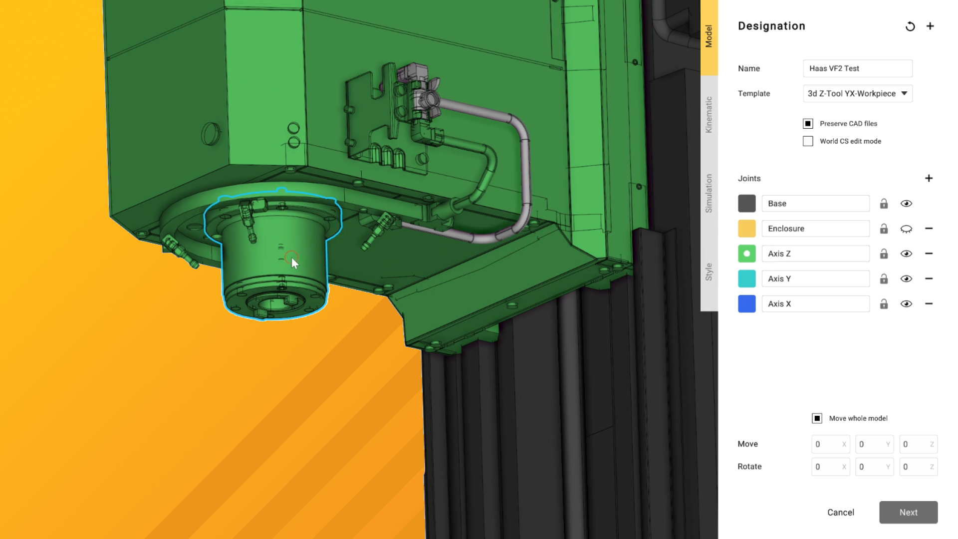
Over the course of these videos, we will import the CAD models and prepare them for use in ENCY, apply kinematic constraints to the models for accurate motion, define the specifics of the machine controller capabilities and finally export the finished schema to ENCY.
We’ll also expand out into incorporating extra axes – perfect for upgrade time in the workshop!

Leave a Reply