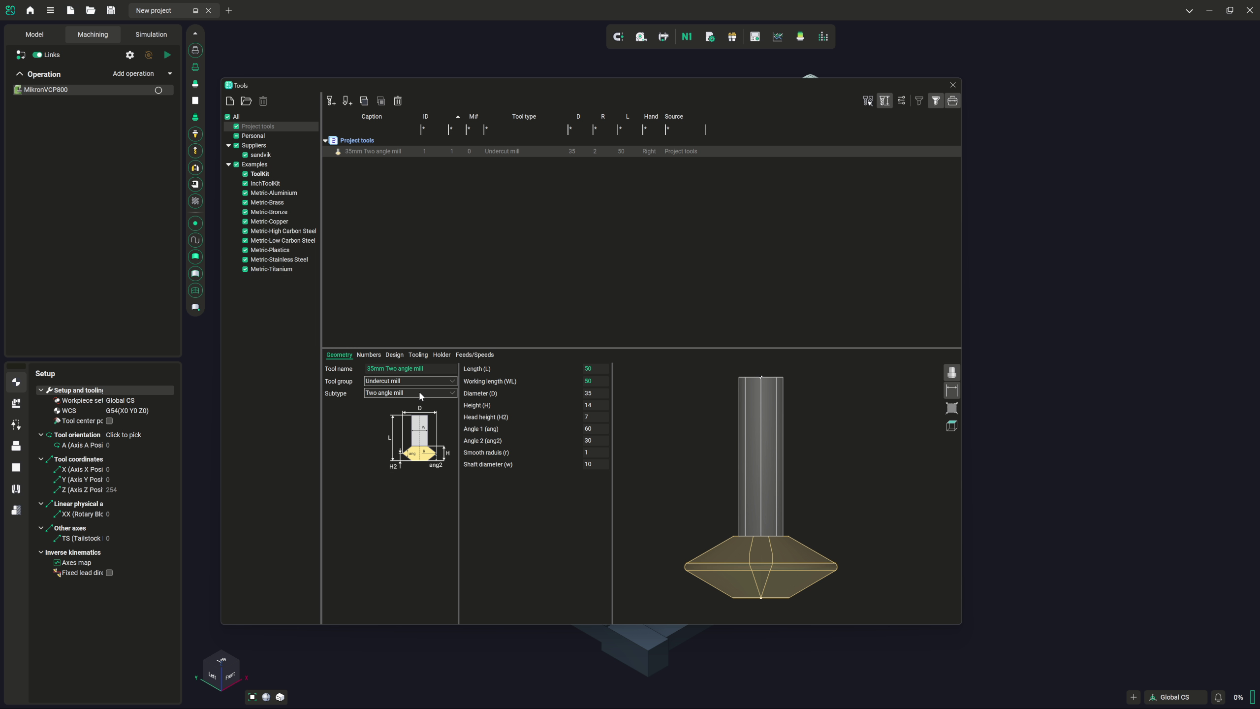
Custom tool definition is part of Defining your own custom tools. Sign in with your ENCY account to access lessons, assignments and progress tracking.
Sign inRead the full text version — the video itself requires sign-in.
Hi there. Today we are going to talk a bit about the tooling options available in ENCY. We have got a very, very comprehensive set of options available to us. And while obviously in the tutorials thus far, we have basically gone through the process of just showing standardized tooling and importing tooling from predefined tool tables, I am now going to go through in a bit more detail the available choices and how to edit and manipulate those choices to be tailored to your needs.
So first things first, where are the tools hiding? So we are going to have a look up here and in this top menu bar here, we have got our tool options button here. So we have got the import cutting tools to the project or save our current list as, as well as the ability to purge any unused cutting tools that we have defined as well, just to keep things tidy and easy. But if we click on this button itself, we are presented with a window, which gives us seemingly an overwhelming range of choice right now.
Now, obviously this is just presenting absolutely everything in front of us, lathe tooling, milling tools, all manner of stuff. And it's not a very helpful thing to see straight off the bat. So I tend to just click on project cutting tools initially, and this opens up a blanked out window at the very start of a project where we can either import and set up the cutting tools that we specifically have loaded into our machine, or we can do it on an operation by operation basis. Again, it's entirely down to your preferred workflow, but right now I'm more interested in showing you what it is that you can use and what's at your disposal.
So while we have these example tools here, which have been the specs of which have been provided by various suppliers and so forth, which is very, very helpful. We're going to define some tools by ourselves at this point. And the process for doing this, we have these two buttons here. We can add a new milling tool, or we can add a new turning tool.
Now, obviously the machine that's in front of us at the moment is a milling machine. So let's very quickly just focus on milling tools for now. So we add a new milling tool and we start out by default with a 10 millimeter cylindrical mill. So a standard end mill, nothing particularly fancy there.
Obviously we can define things like diameter, length, working length, shoulder, shank, and the tapers. That's all pretty normal geometry. If we just move this up a little bit, so we've got a slightly clearer view of what we're looking at there. We can also set things like where it is in our tool carousel, again, under the numbers here.
So we've got the cutting tool number, the magazine number, all of these sorts of things. So these again are stats that are specific to your machine and your machine setup. We can edit the design of the tool, which allows you to define whether or not it's a left or right-handed tool, what units you want to use to define it, how many cutting teeth it's had, what the maximum ramp angle it's okay to operate at is. You can also, again, the tooling is the same as the geometry setting effectively with the definition available for working out where the contact and cutting tool points are in relation to the overall cutting tool itself.
So the contact point being where you want it to actually meet the workpiece and which end of the tool is the point at which it's mounted into the actual holder. So that's quite useful for things like wire bows, that sort of thing as well. So worth noting. Holder, we've already gone through in a separate video that allows you to either import standardized holders, develop your own given the dimensions, the lengthy way, whatever it is that's appropriate for your needs.
Importing standard 3D files is by far and away the quickest and easiest way to do this. And finally, the feeds and speeds definitions. So we do have a calculation built into this where you define revolutions per minute and spindle speed range and all that sort of stuff. Again, that's entirely down to your cutting tools, your machine, your materials.
I'm not going to advise you on how to set your feeds and speeds beyond suggesting. Listen to your machinists and read the spec on the cutting tools you're using. Going back now to geometry, we have over here, we've got tool group and subtype. Now, subtype is not something that tends to come up very frequently in this.
However, cutting tool group is where the interesting stuff really goes on. So right now, we have a cylindrical mill in front of us. Fairly bog standard. Everyone knows what they're doing with the standard end mill.
However, if we click on this drop down menu here, we can see now that we're actually presented with quite a few different options for different cutting tool types. And I want to demystify what some of these are. So cylindrical mill, fairly standard end mill. Spherical mill is a bullnose end mill.
A torus mill allows us to define a radius for our end mills. So that's assuming we're slightly rounded off edges on the end mill. Very, very nice for finishing and so forth. A double radial mill, again, allows you to define multiple radii on your cutting tool.
But we want to apply a corner radius of two. And we can see now how that has completely altered the curvature of the tool there. Again, very, very useful. Once you start getting into the realms of specialized cutting tools, this sort of stuff does come up fairly frequently.
Next, we have a limited double radial mill. Now, this allows us to set slightly more complicated radii. Whenever you see the term limited on the naming for a tool in ENCY, it typically means it's effectively like the tool has been cut off partway. So as you can see in this demonstration here, you've got your standard radius applied, you've got your corner radius, you've also got a flat base as if that radius was supposed to follow through further and then got snipped off.
Again, this is entering the realms of highly customized tooling at this stage. It's useful to have at your disposal. And obviously, if it is the kind of cutting tool you use, this makes it much, much simpler to set one up. We also have conical mills and limited conical mills.
Now, again, my background working in robotic machining, we use conical mills quite regularly. And we did also use limited conical as well. So a conical mill allows you to set the taper along the length of the end mill. In my case, one of the ones that I used was a 320 millimeter long end mill where 200 millimeters of that was on a conical taper.
Again, to most people working with milling machines, that sounds kind of insane in terms of dimensions. But for robotic machining, that's pretty normal. A limited conical mill, again, does the same. But as we can see in this demonstration image here, which is rather unhelpfully not zooming, you can also define a truncated end for that, which is, again, quite useful in some circumstances.
We have engravers, which are quite often just D-bit cutters, although they can sometimes come with multiple flutes. It's not that common in my experience, though. We have the standard drill options. So we have a normal twist drill.
We have a spot drill, which is the limited length flute spotting drill for marking out points. We have center drills, which anyone that's worked with manual machines will know what a center drill is. It's just a stepped spotting drill, basically. We also have reamers available for just cleaning out those bores that you've made, countersinks, counterbores, and boring bars as well.
Now, boring bars are typically calculated by their absolute exterior diameter. So if you are using a variable adjustable boring bar, like you would on a milling machine, you will need to take account for that when you define your cutting tools in this. There are also a couple of options here. So say you've got a back boring bar as well, which, if you're dealing with recessed slotting and everything, that's a very, very useful tool.
Again, though, it does require that you calculate it quite carefully. So, yeah, your mileage may vary, obviously. All standard caveats apply here. We also have standard tapping tools, threading mills as well, with as many different steps in there as you need, which is obviously very, very useful to have.
Mills with negative radio. Now, this is something that you'd probably see a bit more often in the world of CNC routing, although you do obviously get it in milling as well, where you can define a profiling bit. Mills with negative radio. Now, this is something that you'd probably see a bit more often in the world of CNC routing, although you do obviously get it in milling as well, where you can define a profiling bit.
It is possible to do slightly more elaborate ones as well. You can under design, I think. Nope, disregard that, sorry. Yeah, no.
So, moving on, we have undercut mills. Now, this is probably best described as a dovetail cutter in this instance, but we do also have multiple different types here. This is where the subtypes really come into play. So, we've got things like larger slot mills and everything for doing T-slots, lollipop mills for any kind of rounded groove that needs to go in.
Two-angled mills, again, if you want to deal with a double taper or you need to produce a pair set of V-slots opposing each other. Two-angled mills, again, if you want to deal with a double taper or you need to produce a pair set of V-slots opposing each other. Again, these are actually pretty common these days. Barrel mills, which I must admit, I personally have never worked with, but I know that they are something that was requested.
Again, these are actually pretty common these days. Barrel mills, which I must admit, I personally have never worked with, but I know that they are something that was requested. because that kind of flexibility does get demanded in jobs, as we all know. We've also got capacity for dealing with drag knives.
Now, these, if you don't know, are typically, well, they're articulated tools that don't spin. They're just reliant on pressure, much like with, say, a vinyl cutter. As I say, drag knives are often used in things like etching and engraving or in cutting thin, fairly flexible material that wouldn't survive rotary tooling very well. Often in soft plastics or fabrics, drag knives are used.
We have saw blade definitions as well. Now, the thing that's worth noting in this instance is that the saw blade angle is typically in line with what the spindle would be as well. So, it's assuming that you've got your saw blade mounted directly as opposed to how it would be if, say, it were a very, very thin cutting disc in an arbor instead. Okay, so think circular saw, not slitting saw for this.
If you need to define slitting saws, I tend to find myself using a standard cylindrical mill definition with a thin shank and a very wide mill tool. Beyond this, we have a jet cutter, which is pretty much the set of tools that allow you to define things like plasma or laser or water jet definitions as well. After this, we have spray. Now, spray is an interesting one.
Spray allows you to define standard spray paint definitions, but I have also personally, in my experience, found it's actually rather good as a means of defining things like inspection tools or 3D scanners as well. So, if you were to define your tool holder for, say, a 3D scanner as the shape of the scanner, and then you define a full cone spray gun, for example, from the lens points of the scanner, then you actually get a very, good tool path for being able to do 3D scanning around an object, as well as an indicator of where full coverage has been since spraying, when simulated, does apply a color to your object in the simulation. Ultimately, we have probing as well. Now, probing is something that we will be touching on as well.
No pun intended, of course. There are definitions that allow for feedback through your post processor as well for adjusting the frame and placement of objects, but for pure sanity checking, the standard probing configuration works just fine. And finally, we have our gripper definitions. Now, we have empty gripper and single vacuum gripper defined here.
Obviously, if you need anything more elaborate than that, that's something that needs to be defined within MachineMaker for your specific tool and machine setup. So, say you're using an articulated gripper on a robot, or you're using a large panel gripper for moving panels on and off of pallets on CNC routers, for example, or flatbeds, then you will need to define the exact form of your gripper, and use this as your center point for the tool definition. So, we've now covered the core basics in the milling tooling, so we can delete this tool. And if we take a very quick look at the turning tools, fortunately, due to the world of turning being a little bit more fixedly organized, shall we say, we have got standard insert types listed here.
And if we take a very quick look at the turning tools, fortunately, due to the world of turning being a little bit more fixedly organized, shall we say, we have got standard insert types listed here. So, we've got our standard parallelogram rhombic triangular trigon forms here, along with the round and the square as well. We also have the coroturn prime definition as well, which I believe is a Sandvik tooling convention, which allows for multiple angles of approach with the same cutting tool. And finally, we have undefined as well.
So, say, for example, there is a particular profile tool or some kind of workshop developed specific tool that does one job and one job only, but you need it within your machining operations, you can build that here. It's also worth noting that under design in turning tools, you can actually define the specific cutting direction that the cutting tool is to be applied for. And you can also tweak all of the definitions of your tool holder since standardized tool holders are in expected form overall, but the specifics of the shape you can define here, as well as all of the specifics for your actual cutting tool insert as well. Now, I appreciate this has been rather wordy and I've been banging on for nearly 20 minutes.
I do hope that this has helped demystify some of the setup of cutting tools within NC4U. If there's anything that you feel is not covered or anything you'd like more detail on, please do feel free to reach out. I'm always happy to take suggestions and requests on new video content. I hope to see you in the next video.
Take care.