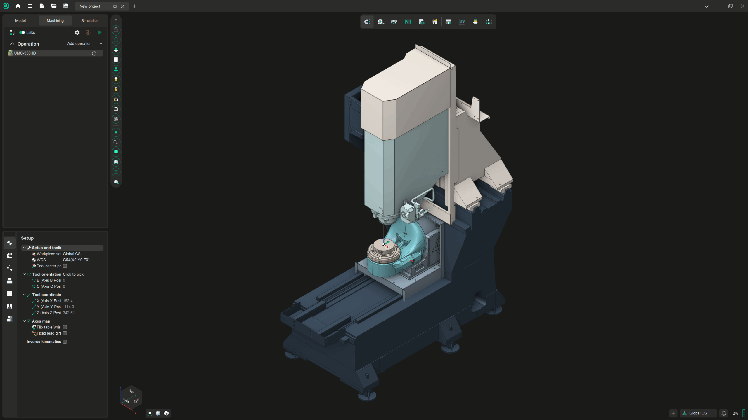
Sign in to watch this lesson

Building and Rigging a Haas UMC 350HD from CAD files is part of MachineMaker: Setting up a Five-Axis Milling Machine. Sign in with your ENCY account to access lessons, assignments and progress tracking.

Sign in

Read the lesson

Read the full text version — the video itself requires sign-in.

So this video is going to be about setting up a 5-axis milling machine and the various processes required to achieve that. So again we're going to be using a Haas milling machine since Haas quite generously donates all of their CAD models for free and available use. So let's make a start. Now I'm going to bypass all of the MachineMaker simplifier utilities at this point since we've already gone through that in the prerequisite course and I'm just going to directly add the mechanism at this point.

So I'll click on add mechanism and go to milling machine and I'm going to grab the relevant STEP files. So let's grab that one and we'll just wait a minute or so for it to import and fully load. Which should only take a minute or so obviously it depends upon the speed of your machine. We will be able to trim out some of the unnecessary elements within this machine as well which will be an automatic function of MachineMaker as opposed to having to go through the full hierarchy.

But obviously it's good to know how to go through the full hierarchy as well hence me covering it in the previous lesson set. So once this is fully populated the first thing that we're going to have to do is we want to rotate it so it's in the correct orientation. So we need to rotate this by 90 degrees in X and that gives us the correct placement and setup of the machine and we're also going to change the template type. Because at the moment it just thinks this is a standard 3-axis machine which it very much isn't.

So if we scroll through the options here we are going to go for 5D table table XZ tool. Now the reason for this is because it allows us to explicitly choose what the priority order of the axes is. Now in this instance X and Z are the only mobile axes for the head itself the spindle and the table setup is independent of the spindle itself. So that's the correct setup that we require.

So first things first I'm going to select the enclosure so I can switch all of that off as well. So let's quickly zoom in and do that now and that is the entire enclosure in one go which is quite handy. Yeah let's get the door as well why not make it look complete. So let's now hide the enclosure by clicking on the eye icon there and we've got a few other free-floating components here which are a little bit unnecessary so we can ignore those for the moment.

So I'm now going to define the base so we go back to the base and we choose all the relevant bits for that. And that should be that for now. The next thing we're going to do is we are going to choose the X axis and the X axis is this section here as well as this one. So these two move along these linear rails.

Next we're going to choose the Z axis which is of course the spindle head and housing. So we may need to zoom in and get a couple of the fiddly bits here. Now I appreciate that this looks quite confusing and that there's a lot of extras in here at the moment but these will not be carried through once we've rigged up the kinematics for the machine so I'm not super worried about it for the moment. Again this is purely me demonstrating how to do this for the sake of speed and testing out the machine setup.

If you are preparing a MachineMaker schema for wider usage it is good practice to go through the simplifier process and to strip out all of the unnecessary geometry. Or even to prepare the models in CAD if you want to really drill down on the level of detail that it has. But for the sake of rigging the machine this is the quick and easy way. So after that we are now going to define the Y axis which is this carriage section here and we'll get the little tool probe as well whilst we're at it.

No we're going to turn that off actually because that's attached to the B. No we're not sorry disregard that I've just realized where I was going wrong with that my apologies. So we're now going to define the B axis which is this section and then finally the C axis which is this array of components here. So now it's always worth checking as well to see if there are any bits underneath that we've not spotted so like with this little bit here we'll turn that on.

Now that pretty much does what we need for the moment so I am going to now go to the kinematics tab by clicking on next. And I'm going to wait a second for this to set itself up and just out of shot I am going to open up the details I've got for the table travels. So first things first the X axis we need to define the range of travel for that so if we move this around to a slightly more useful orientation. And we want the X axis to travel from, no we want that to travel from minus 381 to 0 okay.

So it's currently in its zeroed out position and it can travel all the way over this way. The Z axis is going to go from 0 to minus 305. The Y axis is going to go from 0 to minus 356. Now the B axis and the C axis require a little bit more setup and while these numbers may seem a little arbitrary they are pulled directly from the manufacturer's website so you know I'm not just making these up I promise you.

So the B axis we need to define the rotational orientation and order of these axes so for starters the B axis wants to be rotated by 90 degrees in X. Because it wants to turn this way as opposed to this way so let us very quickly turn that 90 degrees like that and we want to snap this puck here. So it's in the center of this axis right here so hold down control grab the puck wait for it to highlight the ring properly and that is our correct placement. We can also define the range of motion for this as well so this moves from 120 degrees positive to minus 45 negative.

So yeah that's good and then we're going to do the same for the C axis which we want to change the rotation back to 0 degrees in X. And we want to again snap it to the center point of this particular bearing plane so hold down control and move that accordingly. And we have got the full range of minus 180 to plus 180 motion there that's absolutely fine. The next thing that we're going to do is we're going to move the workpiece attachment point because that needs to be further up and again remain centered.

So let's zoom in hold down control to move it and once again we're relying on the snapping here we can see the nice orange ring there. Which means it snapped to the center of that circular edge. And the last thing we So if we go back up into the tree here and pan around a bit. So we can actually see some of the locating features that we need we can grab that tool with control again and we can move this so it's in the correct position.

We do need to obviously move around this a little bit sometimes to make sure that we've got everything just so. Because obviously moving a thing in 3D space using a mouse is not the most intuitive thing in the world. There we go so yeah as you can see that's very very slightly high in Z but that's okay we can tweak that slightly. So if we just move that so it's in line with this face.

So that's 0. 5 no 0. 4 I think let's just double check this you zoom right in. And take a look that is just off by a hair so 0.

41 0. 425 will do for the moment. Although obviously this is something that is again entirely determined by the geometry of your machine this is purely just serving as an example. So we can now zoom out and we take a quick look we can see that the general setup looks sound for the moment I'm now going to click on apply so that saves those settings.

And we're going to have a quick look at running the simulation. So we may get errors in this we don't know this is what we can see that everything is currently moving in the correct orientation except the Y axis is. Apparently moving backwards so again this is why having this particular simulation set up is very very useful. And again as I've mentioned previously undoing these minor issues is absolutely trivial all we need to do is double click on the name of the machine in the tree over there as I just did and.

Then we can open up the kinematic tree again and I'm going to click on axis Y now and I'm going to click on invert direction and then I'm going to click on apply so now that that's done we can once again simulate. And we can to be honest we don't need to go through the whole simulation we can literally just simulate and we can see it's now coming forward in the direction we anticipated. Which is exactly what we wanted it to do so now I'm going to close this I'm going to double click on the mechanism once again and just. Because I like my machines to look uniform I'm going to click on style and instead of 3D model colors because again not every 3D model comes nicely colored.

And everything I'm going to give it a For reference as well we can also see that the enclosure has been kept there but it's been dimmed and it's only at 5% anyway. So if I were to turn this visibility on we can see what the overall exterior enclosure is going to look like and you'll notice it doesn't have any of the stuff like the chip auger or the coolant tanks like it did before that's because that's stored in the original model file. But not in what's going to be exported to ENCY afterwards so let's turn that back off and we're going to make sure that everything is named in a manner that we're happy with. So if I click on model again now it will reload the whole model and it will take a minute or so to do so but it does mean we can tweak the name of it so it gives that a second to finish loading itself up.

And working out who it is where it is what it's doing you know the all the normal it's the first thing in the morning kind of questions we all have for ourselves so I'm going to delete that. And I'm going to tell it that the brand is Haas because it is and then I'm going to demo just to be certain. Because you know sometimes stuff does creep in. You when you don't expect it everything's looking good there so far though I'm quite happy with that.

So I am pleased with this what I am going to do though is I'm also going to rename it up here so by right-clicking no sorry by double-clicking on there you can delete any unnecessary. Or whatever you know you can put in whatever it is you want to write on here now finally the last step is to take a look at the assembly settings I'm not going to go through all of the. Settings on this in any great detail because again that is an entirely per machine basis it typically grabs what it typically settings for that format of machine. But again you are going to need to go through all of the available parameters of your actual machine to have the clearest idea as to.

Which of these we're going to be using the primary things to look at are generally the axes to make sure they're all in the correct order and priority the tool change position is something you're going to want to define. So you collisions again we try very hard to just not mess around with those unless we're absolutely 100% certain of what we're doing leads by default. The approach and return leads are generally okay but again it's entirely down to the specifics of your machine sometimes they want you know they don't want the rotational axes to be returned first. Or set up first it's you know again it's a your machine thing sub machines are if there are extraneous machines or bits of automated kit that get added to this as well.

So things like palette changes for example which again not really a concern for us here and now the one thing that I am going to change in the assembly information though is the assembly developer. So I'm going to write this up as test machine just for the sake of being able to keep them separate from the absolutely finalized machines. Which have got all of the parameter settings done right and then after that I'm going to click on apply and we are now going to save this machine and let's go into documents. And ENCY version 2 machines custom schemas.

And as we can see I've already done this one here just as a you know it's it's it's a test process to make sure that it's all good so I'm going to select that folder. And that's now saved now if we click on the export scheme to ENCY button we should see an ENCY window pop up in a second. And let's change this the machine in this tab just to be safe so don't save the project even though it's been modified. And we can now see that we've changed from the micron VCE that was here to this Haas UMC 350 HD.

So that was not a long lesson building entirely on stuff that we've already covered obviously if there are any further details or things that you feel are unclear please do reach out. But that's a very quick rundown on how to set up a full 5-axis machine from scratch in MachineMaker with minimal fuss I hope you guys have a great day and I'll catch you in the next one.